Master the Contrast, Save the Measurement: Solving Automated Inspection Flaws
Wiki Article
We’ve all seen the marketing demos. A shiny new digital microscope sits on a lab bench. The presenter places a sample under the lens, clicks a single button labeled "Auto-Measure," and—voilà!—perfectly outlined geometric measurements appear on the screen like magic.
It looks like a massive time-saver. But once you get the machine back to your own lab and try it on real-world samples, the magic often fades. Circles are misaligned, edges are missed, and the repeatability goes out the window.
Why does a feature that seems so straightforward on paper fail so frequently in practice? It boils down to a mix of physics, optics, and the limitations of computer vision. Here is a breakdown of why auto-measurement struggles—and how to actually get reliable data.
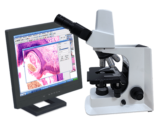
- Smart-E500 Digital Microscope
1. The "Edge" Illusion: How Pixels Deceive Software
For an algorithm to measure a feature, it first has to find where that feature begins and ends. Humans are incredibly good at looking at a shadow or a scratch and understanding the context. Computers, however, only see pixel contrast (changes in brightness).
The Problem: In a perfect world, an edge is a sharp transition from white to black. In the real world, due to optical physics (like diffraction), edges are almost always a gradient of gray pixels.
The Failure: If your sample has a slight slope, a bevel, or a shadow, the software has to guess which specific shade of gray represents the "true" edge. A minor change in your room's ambient lighting can shift that gray pixel boundary, altering your measurement by several microns.
2. The Nightmare of Surface Texture and Glare
Most industrial and biological samples aren't perfectly flat, uniform, or matte. They are machined metal with grain lines, molded plastics with rough textures, or highly reflective silicon wafers.
Hot Spots: Highly reflective surfaces create glare and "hot spots" that completely blind the camera's sensor in specific zones, erasing the edges entirely.
Texture Confusion: If a software algorithm is looking for a line to measure a width, it can easily get "distracted" by a prominent scratch, a grain boundary, or a speck of dust, measuring the defect instead of the part.
3. Depth of Field and Focus Inconsistency
In microscopy, as magnification goes up, Depth of Field (DoF)—the thickness of the plane that remains in sharp focus—shrinks drastically.
If a feature is slightly tilted or has three-dimensional depth, part of the edge will be in focus while another part blurs out. When an edge blurs, its contrast drops, and the auto-measurement algorithm either loses track of it entirely or calculates an incorrect boundary.
4. The "One-Size-Fits-All" Algorithm Trap
Many entry-to-mid-tier digital microscopes use generic thresholding algorithms for auto-measurement. They look for a sudden drop in brightness and assume it’s a boundary.
However, a setting that works perfectly for a dark copper trace on a green PCB will fail miserably when trying to measure a clear glass microfluidic channel or a semi-translucent polymer. Without highly specialized, customizable algorithms for different material types, a universal "Auto-Measure" button is structurally set up to fail.
How to Make Auto-Measurement Actually Work
Does this mean auto-measurement is a useless gimmick? Not necessarily. But to make it reliable, you have to control the variables that confuse the software.
Master Your Lighting: Ditch standard coaxial light if it causes glare. Use segmented ring lights, polarized filters, or darkfield illumination to make the true edges stand out with high contrast.
Standardize Focus: Use motorized Z-axes with reliable auto-focus routines so human operators aren't introducing focus variability.
Program Specific Profiles: Avoid the generic "magic button." Take the time to calibrate specific measurement profiles for specific parts, defining exact contrast thresholds and search zones for the software.
Report this wiki page